What does the CrossScan do?
- Provide numerical values of the percentage coating loss where until now only vague estimates were usual.
- Correct assignment of the cross-cut characteristic value according to ISO 2409.
- Creation of a measurement report with data and images, for documentation, communication and reproducibility of the measurement at any time.
- Helping to lower users' blood pressure through confidence-building measurement rather than estimation.

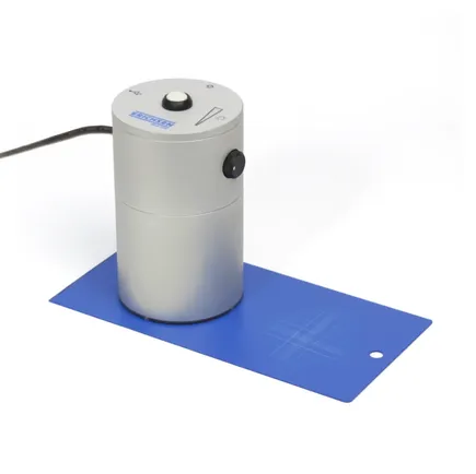
What does the CrossScan look like?
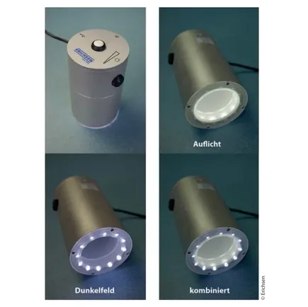
The device consists of a dome to be placed on the grid pattern to be evaluated and is equipped with a digital camera as well as two different illumination units (incident light as well as dark field illumination), which can be combined as required by setting. By connecting it to a computer/laptop, the user can see on the screen what is happening under the dome, i.e. whether the dome is correctly positioned over the cross-sectional grid pattern to be evaluated and what effect the contrast ratio and settings have. The associated software offers an initial automatic adjustment of the contrast via the "assistant" by regulating the "edge sharpness" as well as the possibility of optimising the setup as needed by the user, which becomes necessary at the latest with the individual adjustment of the scribe width definition.
Technical data
- Dimensions: 133 mm high; Ø 75 mm
- Weight (net): approx. 640 g
- Connection via USB 2.0; approx. 300 mA (not via unpowered hub)
- Camera resolution 3.1 MP, (resolution per mm² = 62500 Px)
- Minimum system requirements:
- Processor: I3 or comparable and larger
- Interface: USB 2.0
- Operating system: from WIN7
- Memory: 20 GB free memory or more.
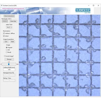
How do you perform a measurement?
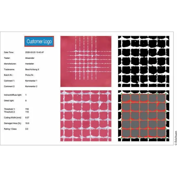
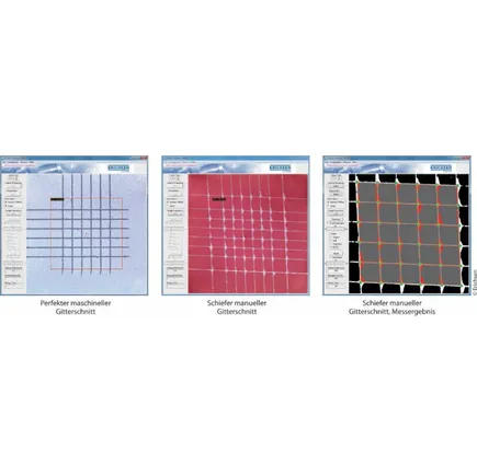
After placing the dome on the cross-section to be evaluated, first the available cross-section size (related to the common standardised cross-sections) is selected, whereby the pattern is marked widely delimited by a coloured frame. Then, by activating the "preprocessing" mode, a binary, i.e. in fact a black/white display is called up at the push of a button, which shows the contrast ratio of the relevant "area of interest" (not influenced by colour shading) available for calculating the percentage coating loss. By pressing another button, a grid is digitally applied to determine the width of the cut channel. After manual adjustment of the width of the cut channel and the user's confirmation of his or her impression in comparison with the original image (the representation must be logical and coherent; it is possible to jump back and forth between all representations for quick and direct comparison), the measurement is completed and can be stored as a measurement report or communicated further.
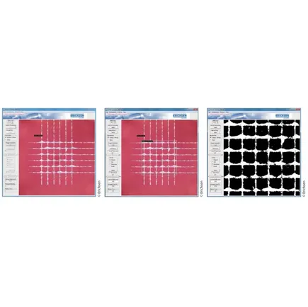
By connecting to a computer/laptop, the user can see on the screen whether the dome is correctly positioned over the cross-cut pattern to be evaluated and how the contrast ratio and settings affect the image. After placing the dome on the grid pattern to be evaluated, the size of the grid pattern first needs to be selected, whereby the pattern is marked by a coloured frame. By pressing a button, a black/white illustration appears, which shows the contrast ratio used to calculate the percentage coating loss.
At the touch of a button, a grid is digitally applied to determine the width of the cutting channel. After manual adjustment of the cutting channel width and confirmation by the user, the measurement is complete.
Measuring principle and realities from the daily practice of cross hatch cutting users
Example of a measurement report
The visibility of detached areas depends entirely on the contrast between the coating and the exposed substrate. To achieve optimal contrast, which can also be effectively detected by software, additional measures can be taken. For instance, a lateral ring light can be activated alongside horizontal lighting to enhance contrast. This ring light accentuates the height differences between the coating and the exposed substrate, further improving contrast. By adjusting the lighting setup through a "trial and error" approach, it is possible to fine-tune the contrast ratio for the best possible visibility, if necessary. Additionally, the threshold value can be manually shifted as needed to appropriately strengthen or soften markings. The progress or status of this initial basic adjustment can be directly observed in live mode.
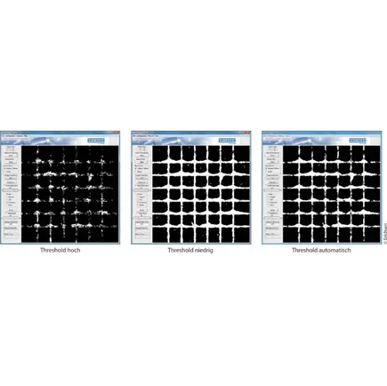
A switchable lateral ring light enables an optimal contrast ratio. Additionally, a threshold adjustment, "Threshold", can be manually fine-tuned to appropriately strengthen or soften markings based on the specific needs.
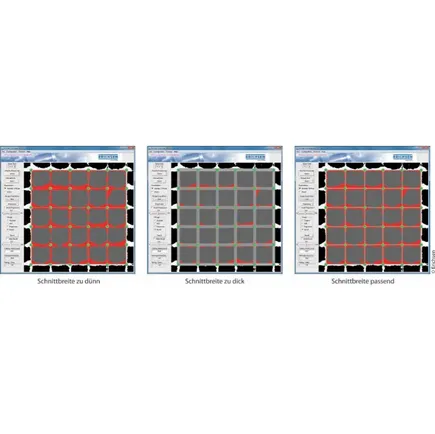
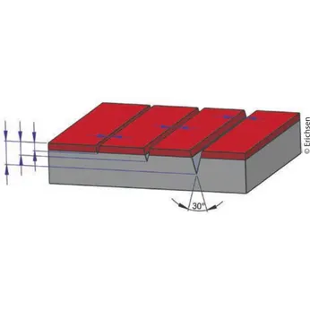
The exclusion of the areas covering the cut channels from the detection must be considered. During the standard 30°-angled cut as per ISO 2409, the depth of the cut directly affects the width of the cut channel. To correctly apply a grid pattern, it is essential to cut through the coating down to the substrate and fully expose the substrate along the entire length of the cut. It is normal and unavoidable in most applications to cut superficially into the substrate, which is fine in terms of the testing process. However, the real-world application presents a different situation: particularly with "soft" substrates such as zinc, aluminum, plastics, and similar materials, cuts often go deeper than necessary. Since re-cutting is generally not intended and undesirable, the user may instinctively apply too much force on the first attempt rather than too little. A grid pattern that is not fully cut through to the substrate is worthless for testing and could generate misleading but better-than-true values. The 30°-angled cut widens the resulting cut channel as the depth of the cut increases, which reduces the size of the square areas evaluated in the grid pattern. As only these areas can be used to assess material loss, the cut channel must be fully excluded. This is achieved through a software-generated grid with adjustable line widths simulating the "cut width", which visually covers the grid pattern as completely as possible. Overlaps or underlaps can be compensated by adjusting the line width until the display appears logical to the user, who can switch between images for optimal clarity. Overall, the user’s impression is crucial for the accurate determination of numerical values.
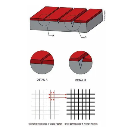
With "soft" substrates, cuts are often made significantly deeper than necessary into the substrate.
Due to the 30° angled cut that opens upwards, the cut channel widens with increasing depth, which progressively reduces the size of the square areas in the grid pattern that need to be evaluated.
What about grid cuts that are clearly not executed at right angles?
Precisely right-angle cross hatch cut patterns are ideal but are rather rare. The already mentioned perfect automatic electromechanical application of grid cuts in the laboratory, combined with CrossScan, represents an ideal scenario – meaning the currently maximal possible degree of excluding user dependency from the topic. However, the overwhelming majority of real-world user scenarios worldwide involve manually applied grid cuts, which rarely meet the strict right-angle standard compared to automatically electromechanically applied cuts.
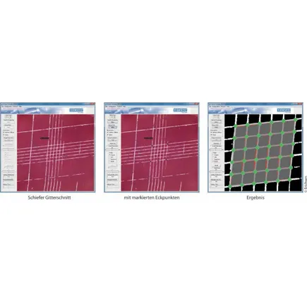
The CrossScan software compensates for this even with a clearly skewed angle and may report detection issues that arise as a result; also when applying the grid to adjust the cut channel width. In such cases, the user can manually mark the four outer corners of the grid with a cursor, and the software will automatically adjust the overlaying grid accordingly.
Where are the limits, what no longer works?
- Curved surfaces, one- or multi-dimensional, with small radii.
- Multi-layer systems with simultaneous adhesion loss occurring on multiple levels within the grid pattern.
- Coating structures without contrast to the substrate or intermediate layer (primer, undercoat, filler, etc.).
- Matching colors of substrate and coating, or possibly primer and top coat.
- Clear coats or translucent/transparent coatings.
- Often, the user can coax usable contrasts by adjusting settings as deemed appropriate, but this must be individually assessed for suitability.
Summary
The capabilities offered by the CrossScan are long-awaited by countless grid-cutting users, marking a significant step towards increased testing security in grid-cutting, for which there was little cause for optimism just recently. Despite all the ongoing customer demonstrations, there is no reason for euphoria as if misunderstanding the quality: "scanning with a measurable value at the push of a button." With all the positive facts, a sober view of the possibilities and limits remains essential to avoid disappointment, as the CrossScan does not replace the user as an independent worker but serves as a new, potentially helpful tool for unmistakable improvement in the globally similar, uncertainty-ridden evaluation situation for grid cuts. In short, the user is still indispensable, but under suitable conditions and with proper use, they feel significantly more comfortable with a large number of typical measurement requirements because they are more objectively reliable – not only the user but also all parties involved in the subsequent documentation and communication chain. Removing dependence on "faith certainty" with a verifiable improvement in safety ("you see, what you get") is a good example of a "win-win" situation for both sides.
Author
Günter Kalinna,
Product Manager Surface Technology,
Erichsen GmbH & Co. KG