Introduction
The formability of thin metallic sheets and foils is increasingly gaining in importance and, therefore, the demand for methods to test the deep drawing and stretch forming capabilities of these materials is increasing significantly as well. Because of the ever-increasing need for resource and material saving, the processing of thin materials is indispensable in the automotive industry but also in medical and food packaging. Additionally, thin stainless steel sheets in the thickness range between 0.05 and 0.1 mm formed by deep drawing, rolling , or hydroforming are expected to greatly reduce weight and manufacturing costs of PEM fuel cells, which is essential to their wider application in the transportation sector. In sheet metal forming, a crack or fracture is a frequently occurring failure characteristic. The time of the crack as well as the strains reached during crack initiation are used in sheet metal forming, especially in sheet metal testing, to draw conclusions about the formability of the sheet metal used. In deep drawing and stretch forming, the in-situ crack detection is either performed manually by purely visual evaluation by the machine operator or automatically by a crack detection system. A method commonly integrated in sheet metal testing machines is the crack detection by analyzing the drop in drawing force. Here, the amount of force drop is determined empirically. In the case of very thin sheets or foils the friction between the ball punch and the metallic sheet acts as a disturbance variable and can lead to a force drop no longer being detectable. Another method for crack detection is the analysis of structure-borne sound. The evaluation of the sound emission during crack initiation, which is low in thin sheets and foils, is strongly influenced by surrounding disturbing noise due to movements in the machine system and interactions between sheet metal and tools, such as vibrations and chatter. Reflected light methods offer another possibility to detect cracks during forming. With these methods, individual light receivers such as light-sensitive resistors or photodiodes are not sufficient; instead, matrices of light receivers in the form of, for example, CCD and CMOS image sensors have to be used. In order to cover the relevant areas of entire components, sometimes several of these image sensors or cameras have to be used. Since the size, shape and orientation of cracks are variable, complex detection algorithms, such as machine learning, have to be used and trained before they can be applied robustly and without errors. Furthermore, homogeneous illumination must be ensured, as unwanted reflections from the sheet metal and the surrounding tools can interfere with the crack evaluation or even prevent it altogether. In order to circumvent the above-mentioned disadvantages of the crack detection methods of the state of the art, a method based on transmission-illumination was developed. Here, the focus was especially lain on sheet material with a thickness below 0.1 mm. In the following, the setup and performance of the new method is presented by applying it to the Erichsen cupping test according to DIN EN ISO 20482.
Development and setup of a transmission-illumination-based crack detection method
In DIN EN ISO 20482 a crack is defined as a fracture that runs through the entire thickness of the specimen and is just wide enough for light to pass through a part of its length. The newly developed and patent pending crack detection method consists of a luminous ball punch – specifically a translucent ball punch with an internal light transmitter, at least one light sensor with receiving optics arranged on the opposite side, and an evaluation unit.
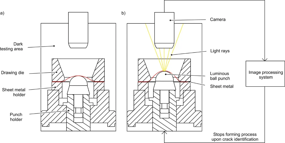
Figure 1. Measurement concept before crack (a) and after crack (b)
The translucent punch penetrates the sheet metal to be formed. The light transmitter, the light receiver, and the evaluation unit have to be activated before the expected cracking of the sheet metal. As soon as a crack forms, light passes through the crack and is detected – directly or indirectly by reflection – by the light receiver. The evaluation unit detects the beginning of the crack by the rapid change of the receiver irradiation. Figure 1 shows the measurement concept before and after cracking of the sheet material. The shown concept uses a camera as a light receiver connected to an image processing system. The measurement system is designed to be portable so that it can be used in a large number of sheet metal forming machines known from the state of the art, in particular sheet metal testing machines. Solely the standard all-steel ball punch has to be replaced with the new luminous ball punch and the camera and image processing system need to be set up. No complex wiring and, therefore, no design adaptations to existing devices and machines are necessary.
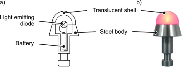
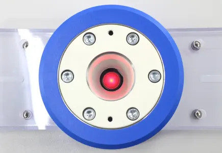
Figure 2. Design concept of transparent tool (a) and manufactured tool illuminated by a red light emitting diode (b)
While the translucent shell of the final series production ball punch is made from alumina-based ceramics with a surface hardness of 1400 - 1900 HV10 and therefore complies with the standard DIN EN ISO 20482, the validation of the newly developed crack detection method was performed using a shell made from 3D printed polyvinylbutyral (PVB). In order to keep the average surface roughness value of the plastic hemisphere as low as possible and to ensure a near standard-compliant forming test with only marginal surface friction, the hemisphere was smoothed with bioethanol. Since the detection method is optimized for metal sheets with a thickness below 0.1 mm, surface pressures in the range of 10-30 MPa are expected, which is well below the tensile strength of 49 MPa of the 3D printed shell.
Contour measurement of the illuminated ball punch
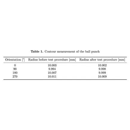
In order to determine the suitability of PVB as a material for the prototype, the hemisphere of the ball punch was measured with a contour measuring device from all sides (90 degree rotation) before and after the Erichsen cupping tests were carried out. The measured values listed in table 1 do not show any significant changes in the tools geometry.
Figure 3 shows the transmission-illumination-based crack detection method applied on an Erichsen model 202 EM, which is equipped with an electrically driven 45 kN drawing cylinder and a Siemens S7-1200 PLC with a Profinet interface. Figure 3a) shows the luminous punch mounted into the machine while figure 3b) shows the camera connected to the machine by a magnetic adapter flange. This adapter flange completely encompasses the camera and sheet during forming and excludes extraneous light from interfering with the measurement process.
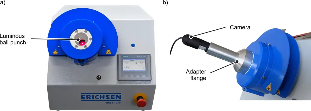
Figure 3. Luminous ball punch mounted into an Erichsen model 202 EM (a) Camera used for crack-detection connected via a magnetic adapter flange (b)
Image-processing
The software specially developed for crack detection during the Erichsen cupping test is programmed to detect the crack at the smallest incidence of light shining through the specimen and immediately stop the ongoing measurement. The 2.0 MP camera used in the test setup shown in figure 3 b) uses an active-pixel sensor and allows capturing frames with a resolution of 1920 x 1080 pixels at a frame rate of 30 fps. It is connected via USB to a PC system, where the image processing is performed using Python and the OpenCV library (Open Source Computer Vision Library). The PC system is connected via Profinet to the Siemens S7-1200 PLC of the testing machine. The overall cycle time of the measurement system achieves a cupping value resolution of 0.05 mm. During testing the evaluation software checks the live image for pixels in the previously defined HSV colour range. Threshold settings can be adjusted by changing the values ”H”, ”S” and ”V” in the HSV colour space via trackbars. The HSV colour space is defined as following: ”H” - Hue (colour angle on the colour circle - 0° for red, 120° for green, 240° for blue), ”S” - Saturation (0% = neutral grey, 50% = little saturated colour, 100% = saturated) and ”V” - Value (0% = no brightness, 100% = full brightness). By assigning Pixels above the threshold to white pixels and pixels below it are assigned to black pixels, a binary image is created. The treshold is adjusted to the light emiting diode illuminating the punch, which emits red light with a wavelength of 650 nm of an light intensity of 125 mcd and an emission angle of 60°. A combined method of binary erosion and dilation is used to distinguish relevant objects from image noise. If the contour length of the object exceeds a certain preset value, the detection process stops. This method removes interfering pixels and ensures that only sufficiently large cracks are detected. Depending on the demands on the metallic sheets and foils, the specifity of the crack detection can be adjusted to meet specific requirements for the material. Thereby, not only the smallest cracks can be detected immediately, but also the size of the crack can be manually adjusted.
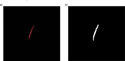
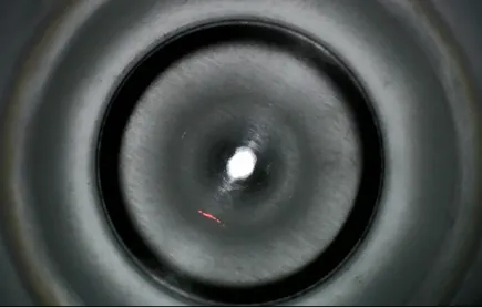
Figure 4 shows the camera image before and after processing. Figure 4 a) presents the live image of the cupping test showing light shining through a crack. Figure 4 b) shows the binarized image used by the software to detect the crack and stop the test.
Experimental validation
The experimental validation was performed using the test setup shown in figure 3. In order to validate the newly developed crack detection method, cupping tests were performed on two different materials: stainless steel 1.4404 with a wall thickness of 0.09 mm and Aluminum 99.5 with a wall thickness of 0.07 mm. To set the cupping results in relation to the conventional procedure, additionally to the automatic crack detection tests with the luminous PVB punch, manual tests were performed using the same PVB punch (without illumination) and a conventional punch made from hard chrome plated 1.2842 steel. In the manual tests, the machine operator observed the forming zone of the sheet with a digital microscope and the process was manually stopped upon the subjective perception of the crack. Tallow is used as lubricant and applied in a thin film, which does not obstruct the crack identification.
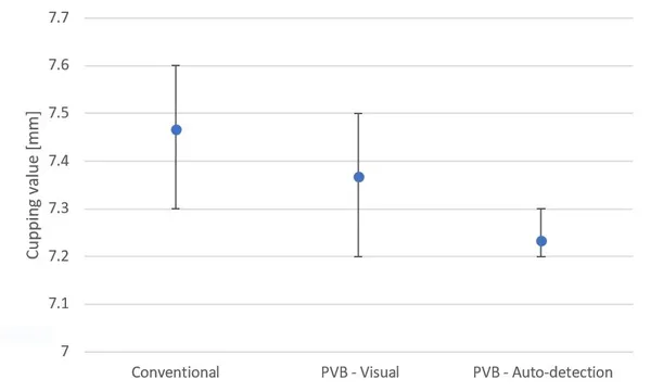
Figure 6. Crack detection on 0.07 mm Al 99.5 sheet metal
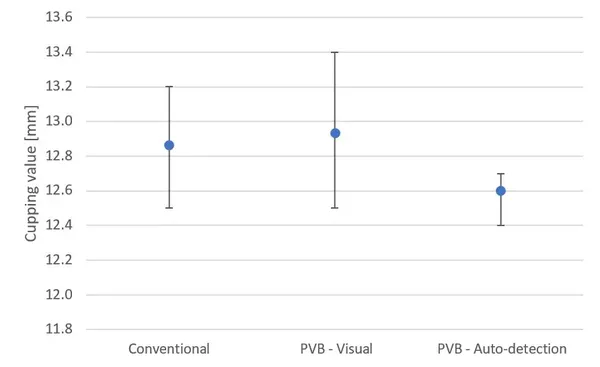
Figure 7. Crack detection on 0.09 mm 1.4404 sheet metal
Based on the measured cupping values, it can be said that the mean cupping values do not differ significantly between the different ball punch materials. Smaller deviations may be related to the quality of the tested material, the different visually determined crack times or the varying reaction times of the operator. On the other hand, the automatic crack detection method detects the appearing cracks much more consistently, as the positive and negative scatter around the mean measured value (indicated in grey) is significantly smaller than other methods. Interfering variables such as user dependency due to visual determination of the crack and reaction time are eliminated from the evaluation. The remaining minor scatter is caused by a combination of the cycle time of the measurement system, numerical variations in image processing, material behavior of the specimens, and friction between tools and the specimens.
Conclusion and Outlook
The newly developed measuring principle is a pioneering development in testing of thin metallic sheets and foils. Not only the previously existing user dependency during these tests is eliminated, complex evaluation algorithms also become more negligible. Further decisive advantages over the currently existing methods are that the method is independent of the friction between the stamp and the sheet or foil, independent of acoustic sounds and vibrations, and independent of the condition of the sheet surface. Since only the light passing through a crack is measured and not that reflected by the sheet, the surface of the sheet or foil can be glossy or matte without affecting the evaluation process. The final series production ball punch battery has an operating time of approximately 10 hours and can be recharged by placing the ball punch on an external charging station. As the alumina-based ceramics ball punch complies with the given standards in DIN EN ISO 20482, Erichsen cupping tests on sheets and foils with a wall thickness below 0.1 mm can be carried out in a standard-compliant and comparable manner.
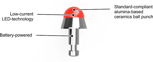
Figure 8. Alumina-based ceramics ball punch for Erichsen cupping tests
Acknowledgement
The investigations were performed in the course of Jan-Luca Schneider’s bachelor thesis: Entwicklung einer automatischen Methode zur Risserkennung beim Tiefungsversuch nach Erichsen an Blechen und Folien mit einer Wandst¨arke von unter 0,1 mm [Development of an automatic crack detection method for the Erichsen cupping test on sheets and foils with a wall thickness below 0.1 mm], South Westphalia University of Applied Sciences, 2021, supervised by M. Marré and D. Staupendahl.
Authors
Jan-Luca Schneider,
Online-Marketing-Manager,
Erichsen GmbH & Co. KG
Dr. Daniel Staupendahl,
Head of Research & Development,
Erichsen GmbH & Co. KG
Ludger Wahlers,
Managing Director Sales,
Erichsen GmbH & Co. KG
Retrieved
04.12.2024 under https://iopscience.iop.org/article/10.1088/1757-899X/1157/1/012075
J-L Schneider et al 2021 IOP Conf. Ser.: Mater. Sci. Eng. 1157 012075
Erichsen Cupping Machines
Classic tests such as the cupping test are still indispensable for the preparation of forming processes. The "illuminated ball punch" cupping test tool is ideal for the Erichsen cupping test on thin sheets and metallic foils up to a thickness of 0.2 mm.
More information