Deep drawing is one of the processes of tension-compression forming as, in contrast to pure deep or stretch forming, there are also local tensile and compressive stresses on the workpiece (e.g. flange on the cup). In practice, many processes, especially in the production of complex geometries such as car body parts, consist of a combination of methods. Generally, however, a hollow body is formed from a sheet blank in each case. It should be noted that in practice, due to the prevailing diversity of geometries, it is not possible to make a general prediction about deep-drawing suitability using a single test method. Therefore, the principle processes are demonstrated in the experiment using the example of cup drawing from flat sheet metal blanks.
Test method
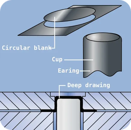
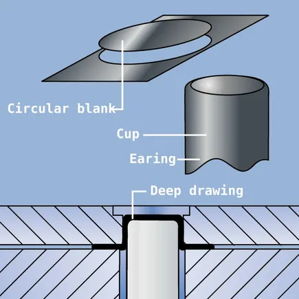
The deep-drawing cup test is a sheet metal testing method in which a circular plate (round blank) is punched out of a sheet metal strip and then formed into a cup by a drawing die. The largest possible ratio between the diameter of the round blank and the diameter of the drawing die, which just allows the perfect production of a cup, is called the limiting drawing ratio >>ßmax<< and is a quality characteristic for the forming capacity of the sheet metal material.
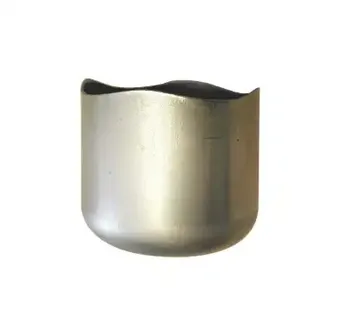
The peaks on the deep-drawn cupa resulting from the flow behaviour of the material are undesirable, as in practice they require unnecessary reworking of formed parts. Also in this case, the deep-drawing cup test can be used to determine the optimally suitable sheet material for the desired forming process.
Key figures
Determination of the deep drawing ratio
The deep-drawing ratio for cups is calculated by dividing the diameter d0 of the round blank by the diameter dS of the punch.
β = d0 / dS
Since the maximum drawing force increases as the drawing ratio increases, a limit drawing ratio results for a single draw, above which failure due to bottom rupture occurs.
For most metals, this limit is β = 2.0 in the first draw, and β = 1.6 in the second draw. Greater forming depths can therefore only be achieved over several draws with possibly interposed softening anneals. The total draw ratio is obtained by multiplying the individual steps:
βges = β1 * β2 * ... * βn = (d0/d1) * (d1/d2) * ... * (d(n-1)/dn)
whereas
βges = d0/dn <= 6,5
This value has proven to be the upper limit in practice. Quantitative statements about the structural changes are provided by the r and n values, which can be used as a measure of the deep-drawing suitability of a sheet.
The r-value
The definition for the logarithmic plastic deformation φ is derived from the law of volume constancy. During deep drawing, the workpiece shows various effects. Essentially, the molecules are displaced against each other, which leads to changes in strength and inhomogeneous (direction-dependent) material properties (anisotropy). To determine the anisotropy of the plastic properties of sheet metal, the perpendicular anisotropy, the so-called r-value, is determined in the tensile test. It is defined as the ratio of the degrees of deformation in the width and thickness direction of the sample. For r=1, the material behaves isotropically and equal deformation occurs in the width and thickness direction. r>1 (r<1) occurs when the sheet changes its width (thickness) more than its thickness (width) under tensile stress. Since a change in shape without a decrease in thickness of the sheet is generally desired, r values >1 are considered advantageous. Due to the multi-axial loading during deep drawing, experience has shown that averaging the r-values from different directions with respect to the rolling direction is useful. For this purpose, tensile specimens are taken from different sheet layers.
A strong deviation of the r-values (Δr) from each other results in an undesired tip formation at the cell in the direction of the largest r-values.
The n-value
The strain hardening exponent n describes the strain hardening of a material during forming. If the flow curve of a material is plotted as a double logarithmic curve, the result is a straight line with a slope of n. The hardening exponent is the highest value of the n-value. The strain hardening exponent for most metals is in the range 0.1 < n < 0.5.
Test principle of the deep-drawing cup test
Deep-drawing cup test for high-strength and ultra-high-strength steels
In the past, tool defects often occurred when carrying out the cup tensile test on high-strength and ultra-high-strength steels, which were due to an acceleration effect at the end of the punching process. By changing the geometry of the cutting ring, the necessary punching force is reduced and the dynamic acceleration of the cutting punch during the punching process is reduced. The tool steel 1.2842 used until a few years ago has been replaced by 1.2379.
Coating the cutting/punching tools with TiCN increases their service life many times over. The cutting gap of the punching tool is increased by approx. 2 - 3 % according to the sheet thickness. High-strength steels show in their forming behaviour that the drawing-in radii of drawing dies no longer meet the specifications of e.g. DC04 steels. Larger radii are specially adapted to materials with high strengths and lower ductility. Drawing dies coated with titanium nitride have a longer service life due to their special surface. Damage caused by cold welding is not possible due to TiN coating.
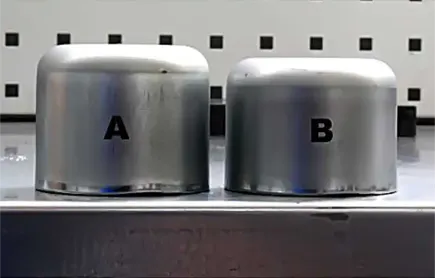
The reduced friction due to the coating can be seen in the height of the drawn cups. Cup A was drawn with a conventional die and cup B with a TiN-coated die made of tool steel 1.2379. The stretching due to friction can be clearly seen by the greater height of cup A.
Evaluation of the earing tendency
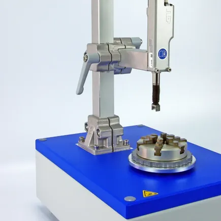
The ERICHSEN Ear Measurement Instrument, Model 126 Plus, is used for the axial measurement of deep draw cups and raw cans. Typical standards are DIN EN 1669 and ISO 11531.
Factors influencing the result are the sheet texture and the deep-drawing process. The detailed parameter determination allows conclusions to be drawn about tool wear and the quality of the deep-drawing material processed. With its flexible concept, the measuring device can also be used for all similar tasks.
More informationEvaluation with Ear Measurement Instrument Model 126
Setup
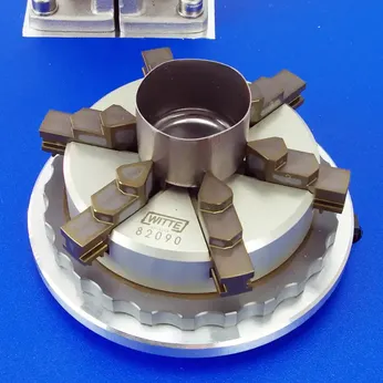
The unit consists of a rotary table, a jaw chuck and a vertical measuring head (with measuring roller and length measuring probe). A jaw chuck fixes and centres the cup. The measuring head can be adjusted to different specimen diameters and heights. During one rotation of the turntable, the measuring head detects the shape of the cup edge, the so-called tippiness.
Measuring process
The operator starts the measuring process either from a PC or from the machine. The test roller, pneumatically activated, lowers towards the sample and the turntable rotates once. After the measurement is completed, the measuring head moves to the home position and allows a quick sample change. The operator reads the measured values from the screen and can archive them as a file. Output formats are .pdf and .txt. The .txt file can be imported into MS Excel. The test report contains, among other things, the following measurement results:
- He_(mm)= Mean earing height
- He,max(mm)= Maximum earing height
- H_(mm)= Mean cup height
- Z(%)= Mean earing height %
- Number of earings
- Date, batch, inspector...
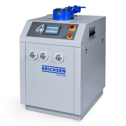
ERICHSEN Testing Equipment
ERICHSEN Sheet Metal Testing Machines are suitable for a large number of forming tests (Erichsen cupping tests, Deep drawing tests, Bulge tests, FLC tests, etc.).
More information